Thursday 23 December 2010

Fly By Wire Architecture

I am somehow inclined towards Airbus than Boeing for many silly reasons. Not that i dont like Boeing, its a wonderful company.They have made some of the most innovative and amazing air crafts. Airbus on the other hand is an EADS company in European region where people speak a lot of languages i like, located in France - a place i want to visit. They have built the biggest commercial airliner till date and so on. Hence, I will be looking into how FBW is implemented in an Airbus aircraft.

Why do we need Fly by Wire? Is it just electronic control instead of conventional ways of controlling an aircraft and having flashy big screens and hundreds of buttons all over the cockpit?? Or is there something else??

There's certainly more.. Fly by wire has a lot of advantages. There is improved flight handling, operating within the flight envelope, reduced maintenance cost and weight. Safety improvements too.

So, how is it all done?

We know that there are both primary and secondary control surfaces to be managed. From the earlier post, its also known that they are controlled by a computer too. The advantage is that there is redundancy at all levels - control surfaces are redundant, computers are redundant, power supplies to these computers are redundant too. There is always a dissimilarity in the hardware and software used on the flight computers so that the common mode failures are eliminated.


The pilot's demands go to the computers. The word "Computer" is so generic here and it is actually a combination of multiple systems together.There are three units within it:


2 Elevator and Aileron Computers (ELAC)
3 Spoiler and Elevator Computers (SEC)
2 Flight Augmentation Computers (FAC)

These computers manage the electrical signaling. Two computers are dedicated to data handling from the control computers for indication, warnings, maintenance and recording purposes.

Thus we have 7 computers to handle the signaling with ELAC using Motorola 68000 IC, SEC using the first of X86 based processors, the 8086 and FAC using the 80286. Can't stop thinking how small and low performance devices these IC's are compared to the Gigahertz processors of today ! Even then,they manage such a huge aircraft !

Different software languages are used for each channel. Popular ones being C and Assembly level languages and usually another custom language developed by the aircraft manufacturer.

Each of this computer is capable of detecting errors in its operations, stop its control over the surface it manages and interrupt the other computer that he is not controlling the surface anymore. However, all the computers will be generating the control signals that are necessary while ONLY one of them is actually controlling it.

The architecture of the FBW System is as shown in the diagram. SFCC is the Slat and Flap Control Computer.


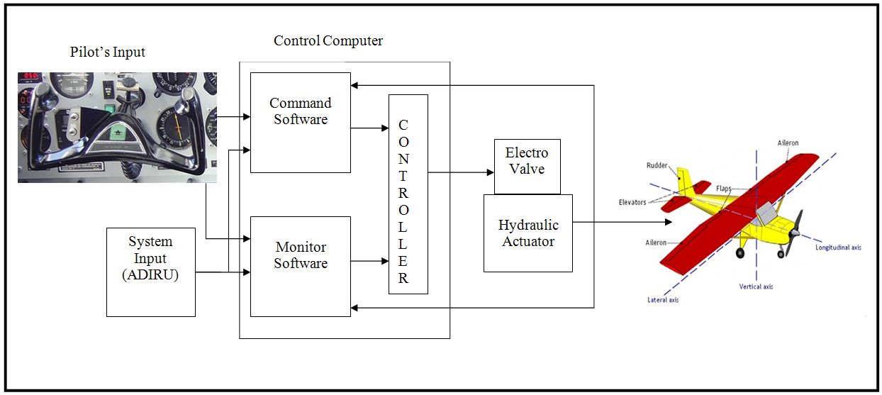
The architecture of each of the ELAC/SEC/FLCC is as shown.

There are two parts, Control and Monitor. Control unit is responsible for generating the electrical signals while the monitor is constantly reading the mechanical movements of the parts. Since all of us are pretty good with drawing and developing our own algorithms and architectures, I'm not going to talk of every single little detail.


At last, when you see both the pictures and try to put the structure of each computer into the FBW architecture and imagine the bigger system in mind, you can see how large and complex the whole of Fly-By-Wire System is :)


After going through all this architectures and all of the technical blah-blah, I'm sure there is a big mystery in your mind :)

What does this all mean to me when i fly ??? !!!


Well, the FBW System will not allow the plane to do manoeuvres which cross certain limits when considering a commercial aircraft. It WILL NOT allow the pilot to pitch more than 15 degrees while in flight and pitch only up to 30 degrees while landing, not bank more than 33 degrees at any point of time so that your drink that you paid for will not spill over you.
Even if the pilot tries to bank your plane to more than 33 degrees, the plane may bank for a while until it has processed that the banking angle is out of limits and the system automatically reduces the bank angle.There are a whole set of rules that are hard coded into the system so that your flight is as comfortable as possible.

This Architecture speaks of how to keep the plane within the operating limits to make sure the passengers enjoy their flight over the clouds. But, there is another much more interesting face to this.How can this be used to achieve the impossible ?? Any guesses of what i am talking about ?

Tuesday 16 November 2010

Fly by Wire

Electronics has been a integral part of my life. I just loved electronics being a kid.. i used to unscrew all the electronic products in the house if it had the slightest problem. Just wanted to hear my parents say "Hey,its not working properly. " Managed to study it too :) and over the past few months i have learned so much more than i studied in my engineering days. Thinking about Electronics and Aviation gave me the idea of writing this post. Another reason is that i am not very satisfied with my seminar which i did in my last year of bachelors. I bet most of the people who heard it had a good slide show of all types of planes, colorful and exciting: D

Anyway, coming back, every design evolves as time passes by. So is the case with aviation. During the early few years, the airplanes that were built were very small and very very simple. It was just a petrol engine with blades at the front and an airframe attached to it. Now aviators wanted a slightly bigger and a bit more features added. Then came the idea of using pulleys and cable links which were added to manage the control surfaces. But trust me, it took Arnold Schwarzenegger's strength to move the pulleys and cables to operate these machines, that too when flying high above the ground and winds hitting you at hundreds of kilometers per hour!! But somehow the pilots handled it.


Then another guy wanted to sit behind and watch the earth below when his friend was flying :) This made the plane larger and it was just not that easy to control by pulleys. So, aviators began using servo motors which were linked to the pilot’s controls by mechanical links and the servo motors movements were in accordance to the pilots inputs. But as you all know these motors were too heavy. And as the size of the airplanes increased, the motors had to be bigger accordingly. This was the driving force to implement the FBW Systems.


Remember very old classical english movies where a bomb is put very far and a very long thread smeared with gun powder extended all the way from the explosive charge towards a safe place and when ignited, it will burn all the way through and then explode?? Coming to today's version of the same scenario, you place the explosive, come very far-press a button- a radio signal is transmitted to it and it explodes.

So, in lay man's words, a Fly by Wire system is very similar. Earlier mechanical and pulley systems go with the old method and the today's version is like an electrical signal goes from the pilot's control to the stand alone mechanical unit near to the control surface.

But that’s just the very higher level of explaining about FBW. I guess i can now move to the architecture of it.

So, as you can see, the pilot’s inputs go to a set of computers. These computers generate the signals to be sent to the mechanical units based on a set of rules. One of them is considering the inputs from sensors which are placed all over the plane which gather information on thousands of parameters every single moment.

Other is getting feedback information from the control surfaces itself because nothing always works as it is intended to!!

The multiple blocks indicate redundancy in the whole system which is a big advantage when compared to older techniques of controlling an aircraft. Remember that if any mechanical link breaks, you have no control over the control surface in the chain. This is not the case with FBW because, there are multiple computers doing the same thing and multiple wires that connect to the control unit taking different paths on the plane so that even if one the wires get broken due to an accident, the other wire which is routed through a different path is still very existent and the whole thing is still operational :)

Fly by Wire is not as simple as it seems to be. Hope this was a good start. Lots of posts related to FBW to come in the coming days.

Saturday 18 September 2010

Heads Up Displays

Well, i was wondering what to write for my next post and i see this video of a BMW with a new kind of display implemented. That reminded me of the HUDs.

How about displaying all the information you need in front of your eyes rather than you seeing it on a display screen?? How about you get to use your mobile with just a pair of cool eye wear without touching or seeing your mobile phone often??

Well,that's how it feels to use a Heads Up Display(HUD).

HUD's came into first use in fighter planes,the idea of which was derived from the static gun sights used in WW2 Dog fighters. HUD's were seen in jets as early as 1958 in the Buccaneer strike aircraft. It was observed that the Buccaneer pilots had better piloting skills compared to other air crafts which had no HUD's. This led to the explosion of this technology in the coming days.

What if you get into a 8 lane straight road in your new car that can go really fast and u want to reach the maximum possible speed without violating any speed limits?? You'll have to constantly switch your vision between your speedometer and the road ahead. But what if your speed was displayed in your line of sight?? You never have to look at your instruments then :) This is the HUD technology being used in the auto industry today derived from the Jets.


So, basically a HUD is a transparent screen on which all the required critical information for the pilot is displayed so that he does not have to look at other dials very often.The origin of the name stems from the pilots being able to view information with heads "up" and looking forward, instead of angled down looking at lower instruments.

Shown below is a HUD from a Gulf stream Private Jet !!


Before reading what all the display mean, i should first tell about headings. Earth is considered as a circle. The North pole is true Zero,somewhere near Japan is your 90 degrees. This means that South pole is our 180 degrees and thus the whole of 360 degrees.

So, if i say that i'm heading 270, it means that from the point i have my plane,i'm heading west.

1.Actual Heading- Informs that the jet is cruising towards heading 244 degrees.
2.Set Heading- Informs that the jet is set to cruise for heading 245 degrees.
3.Pitch Ladder-Indicates the pitch at which the airframe is wrt level ground. You can see a 5 written at the other end of this line. This informs that the plane is at 5 degrees wrt horizontal level.
4.Flight Path Marker- Indicates the direction in which the nose of the plane is heading to.
5.Set Altitude Indicator- can read 24000. Means that the jet is set to fly at 24000 feet above the ground !
6.True Altitude Indicator- Its 23970- means that the plane is flying at 23970 feet.
7.Climb Rate- Reads 1013- means that the climb rate is 1013 feet/second.
8.Bank Angle Indicator- Currently reads 0 which means that the plane is not banked at any angle.
9.This must be some other general flight information about which i am not sure about :(
10.G-force Indicator- Reads 1 G-which implies that the people inside the jet feel the same gravitational force as they would feel on ground.
11.Set Heading- Reads 245 again. Dunno why this is made redundant in the display.

This is as far as i could understand from seeing the HUD. I so much tried to write with a fighter jet HUD,but could not get one with such high resolution as this.

However there is another version of the same heads up display technology- its the Helmet Mounted Display(HMD). Instead of using a transparent screen in the line of sight, its implemented on the helmet of the pilot.This is widely used in the Apache Attack Helicopter. Now, how about same technology on your bike?? The amount of information to be displayed may be far too less,but wont it be nice??


This technology is slowly coming into commercial jets and car industry too. Hope this post is easy to understand as the earlier ones:)

Sunday 6 June 2010

Helicopters


It’s been a while since I last wrote something about planes. My new job had occupied me so much that I could not write about these wonderful machines J Since you all know pretty much about planes, I decided to write something related to Helicopters this time.

The word 'helicopter' is adapted from the French hélicoptère, which originates from the Greek helix = 'spiral' or 'turning' and pteron = 'wing’.


Since its been a few months after I updated this blog, I would suggest you to read my earlier post about how an aircraft flies and all that because -the basic concepts of flight no matter fixed wing or rotary wing, remains the same.

It’s said that flying a Helicopter is far more tough than flying a plane !! This is because of the numerous Stability Controls that the pilot has to take care of while flying it.


Helicopters have rotating blades and a tail rotor as the rotating parts on it. The Elevator is another important part. The rest of the anatomy of the craft is as shown. The Helicopter's spinning blades not only lift it into the air, they are also a means of propulsion-more of a combined wing and propeller. Each of the long, thin blades-the number which varies from 2 to 8, has the aerofoil shape of an aircraft fixed wing and the leading edge of the wing is angled upwards at a small angle.


To lift the helicopter off the ground the blades are rotated and their pitch-the angle at which they meet the airstream- is gradually increased. As a result, air pressure decreases above each blade and increases underneath it, providing the upward force. When the lift beneath the blades is greater than the weight of the helicopter, it rises into the air. This is how it lifts off from the ground.


Once it lifts off the ground, how does it gain height?? Applying more engine power increases the collective pitch of all the blades and lifts the craft higher.


Once the helicopter is airborne, flight is controlled by adjusting the amount and direction of lift created by the blades. The pitch can be altered by two controls - collectively by the Collective Pitch Lever or separately by the Cyclic Pitch Column.


The Collective Pitch Lever angles all the blades at the same pitch. It is used by the pilot for vertical ascents and descents. As the pitch is increased and more lift is generated, the throttle is usually opened up automatically to provide the necessary extra power.


The Cyclic Pitch Column adjusts the pitch of each blade individually as it sweeps around. If the column is moved forwards, each blade’s pitch increases as it passes over the tail and decreases as it passes over the front of the helicopter.


This provides more lift over the tail than the front of the helicopter which makes the whole rotor tilt forwards. The helicopter is propelled in whichever direction the rotor is tilting. So, if the rotor is tilting forward, the craft flies forward. To change the direction while hovering, the pilot can use two foot pedals to change the thrust of the tail rotor and swing the craft’s tail around.


The Tail Rotor is a very small part of the whole craft, but one of the most important parts!! The tail rotor provides the directional control at low speeds and in Auto rotation[ A condition where the engine has lost the power and the blades can be kept spinning to glide the machine down to the ground]. Also when the helicopter is hovering, it counteracts the tendency of the fuselage to move in the opposite direction to the blades- called as Torque Reaction.


For single engine helicopters, the tail rotor is essentially a torque eliminator. However some helicopters eliminate torque by using two rotors or by having two sets of blades spin in opposite direction along the same rotary axis.

So, now that controlling the pitch of the blades is known, how does the helicopter do all that maneuvers??


Flying Forward


Easing the Cyclic pitch column forwards gives more lift over the tail of the helicopter. This causes the rotor to tilt and propel the craft forward at a constant altitude.


Flying Sideways


The pilot just moves the Cyclic Pitch Column to the direction he wants to go, causing the blades to give more lift on one side than the other. The rotor tilts and propels the helicopter in the chosen direction.


Hovering


Now this is an interesting and entertaining show to see a helicopter hover. To hover, the pilot adjusts the pitch of all the blades with the Collective Pitch Control so that the amount of lift generated b the rotary wings just exceeds the weight of the helicopter.


Flying Backward


By easing back the Cyclic Pitch Column, the blades are given more lift as the pass over the front of the craft than over the back, so the rotor tilts backwards enabling the helicopter to fly backwards.


Versaitily but not Speed !!


The maximum speed capable by helicopters is around 400 Kmph. This is because around that speed, the blades are travelling at the speed of sound at which all the normal aircraft encounter drag and lift problems. The retreating blades are however travelling at a lesser speed than the forward speed of the copter and can scarcely generate any lift.


Although the engines provide abundant power, most of it is used for Lift. An Aero plane with a similar engine would fly much farther and much faster for the same fuel consumption. This is the tradeoff between Versatility and Speed and Fuel Economy.

Future


The problems with Stability and other design aspects led to the abandoning of helicopters for nearly 30 or more years in favor of fixed wing designs. However, with the invention of jet engines and other developments in fixed wing designs, the situation has changed. Though mot much can be speculated, the future of helicopter design seems to lie in a Hybrid Aircraft capable of acting as a part helicopter and part plane- called as a Tilt-Rotor Aircraft.